•   |  

Single Tension Tester

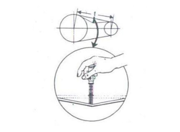
How to Tension Multiple V Belt Drives

With Your Gates Tension Tester

  1. Measures the Span Length(t)
  2. Position the lower of the two O-rings using either of the following methods:
    1. On the scale of reading “ Deflection Inches,” Set the O-ring to show a deflection equal to 1/64” per inch of span length(t).
    2. On the scale reading “ inches of Span Length,” set the O-ring to show a deflection equal to the inches of measures span length(t) Read scales at the bottom edge of O-ring. Leave the upper O-ring in maximum up position.
  3. At center of span(t) apply force, with Gates Tension Tester Perpendicular to the span, large enough to deflect one belt on the drive until the bottom edge of the lower O-ring is even with the tops of the remaining belts. A straight edge across the belt tops will insure accuracy of positioning.
  4. Find amount of deflection force on upper scale of Tension Tester. The sliding Rubber “O-ring” slides down scale as tool compresses — stays down for accurate reading of pounds presser. Read at top edge of ring. ( slide ring up before re-using)
  5. Compare deflection force with range of forces in tables below. If less than minimum recommended deflection force belts should be tightened. If more than maximum recommended deflection force. Drive is tighter than necessary.

RECOMMENDED DEFLECTION FORCE PER BELT

(For Hi-Power II V-Belts & Power Band and Tri-power V-Belts)

V Belt Cross Sections Small Sheaves Diameter Range ( inches) Small Sheaves RPM Range Speed ratio range Recommended deflection Force ( Pounds)
Hi-Power II & Power Band Tri - Power
Min Max Min Max
A 3.0 1750
To
3600
2.0
To
4.0
2.7 3.8 3.8 5.4
3.2 2.9 4.2 3.9 5.6
3.4 - 3.6 3.3 4.8 4.1 5.9
3.8 - 4. 2 3.8 5.5 4.3 6.3
4.6 - 7.0 4.9 7.1 4.9 7.1
B 4.6 1160
To
1800
2.0
To
4.0
5.1 7.4 7.1 10
5.0 – 5.2 5.8 8.5 7.3 11
5.4 – 5.6 6.2 9.1 7.4 11
6.0 – 6.8 7.1 10 7.7 11
7.4 – 9.4 8.1 12 7.9 12
C 7.0 870
To
1800
2.0
To
4.0
9.1 13 12 18
7.5 9.7 14 12 18
8.0 – 8.5 11 16 13 18
9.0 – 10.5 12 18 13 19
11.0 – 16.0 14 21 13 19
D 12.0 – 13.0 690
To
1200
2.0
To
4.0
19 27 19 28
13.5 – 15.5 21 30 21 31
16.0 – 22.0 24 36 25 36
E 21.6 – 24.0 435
To
900
2.0
To
4.0
32 47
Tension tester accessory image 1
Tension tester accessory image 2

Note : There will normally be a rapid drop in tension during the “run – in period” , Tension new drives with a 1/3 greater deflection force than the maximum force recommended. Check tension frequency during the first day of operation.


Recommended Deflection Force Per Belt
For Super HC* V-Belts, Super HC PowerBand * Belts,
Super HC Molded Notch V-Belt or
Super HC Molded Notch Power Band Belts

V- Belt Cross Section Small Sheave Diameter Range ( Inches) Small Sheave RPM Range Speed Ration Range Recommended Deflection Force ( Pounds )
Minimum Maximum
3VX 2.20 1200 – 3600 2.0
To
4.0
2.8 4.1
2.35 – 2.50 1200 – 3600 3.2 4.7
2.65 – 2.80 1200 – 3600 3.5 5.1
3.00 - 3.15 1200 – 3600 3.8 5.5
3.35 – 3.65 1200 – 3600 4.1 6.0
4.12 – 5.00 900 – 3600 4.8 7.1
5.30 – 6.90 900 – 3600 5.8 8.6
5VX 4.40 – 4.65 1200 - 3600 2.0
To
4.0
9.0 13
4.90 – 5.50 1200 - 3600 10 15
5.90 – 6.70 1200 - 3600 11 17
7.10 – 8.00 600 - 1800 13 19
8.50 – 10.90 600 - 1800 14 20
11.80 – 16.00 400 - 1200 15 23
C 7.10 – 8.00 600 - 1800 2.0
To
4.0
11 16
8.50 – 10.90 600 - 1800 13 18
11.80 – 16.00 400 – 1200 14 21
8V 12.50 – 17.00 600 – 1200 2.0
To
4.0
28 41
18.00 – 24.00 400 – 900 32 48

*If replacing 3V or 5V belts with the same belt length and same number of belts in 3VX & 5VX cross section, Belt tension does not need to be increased.


Note : New Drives designed with 3VX or 5VX belts Should be tensioned at the respective deflection force value shown in the above table.

Talk to us?